Abstract
Understand has a lot of different graphs that use the display area quite differently. Natasha goes into detail about how we determine what to display for that critical initial view of a graph.
Details
One of my bosses favors terse directions. In this case, I was told: “Make the initial view of a graph in Understand interesting.”
The initial view of a graph is something that’s being constantly improved and has received a lot of thought from several engineers. One of the main things we prefer to avoid is having the initial view of the graph appear empty. This used to happen a lot in large graphs where the top left corner is often empty.
So, instead of always defaulting to the top left corner, the first step is to identify something to focus on. That “something” is likely to change depending on the graph, and there are a lot of graphs in Understand. However, most graphs have a “root” node, a starting point that is usually an entity or an architecture.

Graphs have been searchable for a long time, so a first pass is looking for the root node’s name using the existing search functionality. Once the label is found, we can ensure that position is visible with the scroll bars. There are some downsides to this approach, for example, it may get confused if there are multiple nodes with the same name.
So we do a second pass that finds the root node using the metadata associated with each node. Most nodes are tied to an entity or architecture, which is how syncing and right-click menus work. So, that metadata is searched instead of directly searching the text. A second change was also possible now that all graphs have been standardized to use the same view class. Some graphs used to be drawn a different way, but everything was unified to Qt‘s QGraphicsView when the default graph navigation was updated. With QGraphicsView, the root node could be centered instead of only being visible, and if the entire graph could fit on the screen, then the whole view was centered.
Personally, since I’m not an art major, I was fine with centered views. But I was informed by artistic people that centering is not very interesting. I guess there are things like a rule of thirds and perspective and so forth that art majors learn about.
While I may not know all the art theory, I understood that the root node ought to be off-centered. Off-centered how? I got replies like “Well, with that Calls graph, start more towards the left edge, but if it were a Called-By graph, then towards the right edge, unless the layout is vertical and then it would be the bottom edge for the Called-By, oh and for the butterfly graph centering is ok, …”
The main problem with these examples is how graph-centric they are. By the time a graph is displayed, the renderer has no idea if the graph layout was vertical or horizontal or what the scope was (forward for Calls, reverse for Called-By, or Butterfly). Rather than add a lot of reverse-engineering logic for various graphs, it would be better to find a generic solution.
With the Calls and Called By graph, the root node is on an edge, and the gist was that the root node needed to be closer to whatever edge it started near. Since the dimensions of the scene are known and the position of the item is known, it’s possible to determine the distance to every edge.
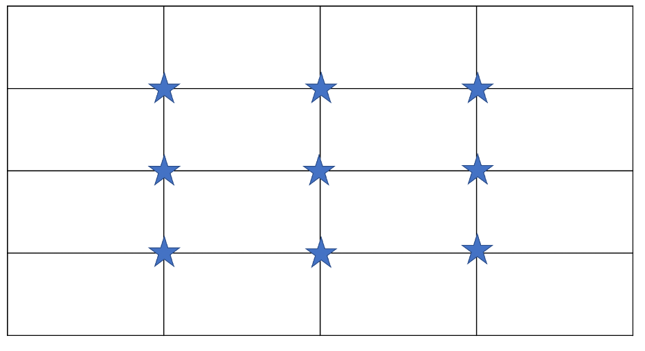
To start with, I focused on the left and right edges and ignored vertical layouts. As an arbitrary decision, I split the width into 4 parts. I probably should have used 3 for all the art majors, but it seems to work. If the root node is in the left quarter of the scene, then I want it centered on the left quarter line of the visible rectangle. If the scene is in the right quarter, then I want it centered on the right quarter line of the visible rectangle.

In the code snippet, mTrackDelta is a QPoint holding the offset for the root item from the center (because I’m still using QGraphicsView::centerOn() to control the final positioning).
This code worked surprisingly well (once I got my negative signs correct. I’m a little directionally challenged). So, I added it for the top and bottom too, as a separate conditional, making 9 possible places for the root node to end up:
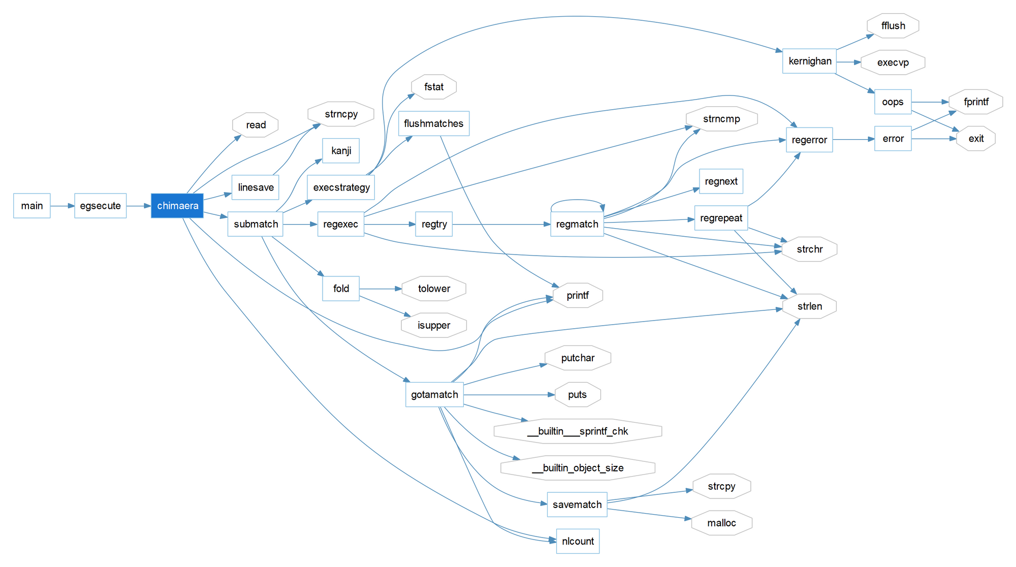
But, the Called By graph for Chimaera ended up here:
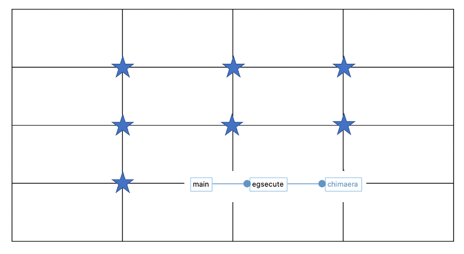
When I wanted it here:

The problem is that the position used is not necessarily the visible center of the node. It’s localized on the label (so it works better with clusters) and can be offset. So, it should only count as being in a particular quadrant of the scene if the scene is some amount bigger than the node’s bounding rectangle. What amount? I tried testing the quarter size, but that didn’t work in all cases. So, as a new arbitrary number, the scene must be at least twice as big for the node to end up off-centered on that axis. Final code:

Is it more interesting? I’ll admit now that it’s working that I like it better than my initial centering approach. Artistic people will have the final vote when it gets released.

